

How To Test Control Board On Refrigerator
Key Points
- Step-by-step instructions on how to troubleshoot and replace a GE Refrigerator chief control board
- Instructions on installing Part # WR55X10956 and WR55X11064
Table of Contents
- Applicative Models
- Location
- Maintenance – Visual Inspection Tips
- Input / Output Specs
Applicative Models
| GE Model | Part # | Name | Replaces |
|---|---|---|---|
| PFCF1NFW (PFCF1NFWAWW | WR55X10956 (Check here for the latest availability and cost) | Chief Control Lath Assembly (computer logic lath) | 1550509, AH2371144, EA2371144, PS2371144, WR55X10657, WR55X10658, WR55X10662, WR55X10697, WR55X10745, WR55X10774, WR55X10929, WR55X10943, WR55X10958 |
| PFCS1NFW | Run into PFCF1NFW | Main Command Board | Run into PFCF1NFW |
| PFIC1NFW | Come across PFCF1NFW | Principal Control Board | See PFCF1NFW |
| PDCF1NBW | See PFCF1NFW | Chief Control Board | See PFCF1NFW |
| PFCF1NFC | WR55X11064 ** | Main Control Board | WR55X10697 |
| PFCF1NFX | WR55X11064 ** | Main Command Board | See PFCF1NBW |
| PFCF1NFYA | WR55X11064 ** | Main Control Lath | Meet PFCF1NBW |
| PFCF1NFZ | WR55X11064 ** | Main Control Board | See PFCF1NBW |
| PFCF1NJW (PFCF1NJWABB, PFCF1NJWACC, PFCF1NJWAWW) | Main Control Lath | Come across PFCF1NBW |
** Y'all may see a sticker on the backside of your refrigerator that states "ATTENTION: Utilise Simply MAIN Board SPECIFIC VARIABLE SPEED COMPRESSOR. REPLACEMENT Part NUMBER WR55Xxxxx". Please notation that all role numbers listed in the above table are the latest data obtained direct from GE Apparatus Parts.
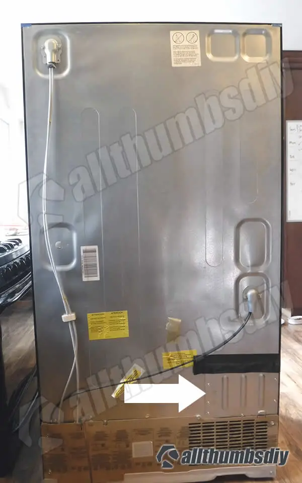
Location
Main control board is merely accessible via rear panel of your refrigerator.
Model PFCF1NFW chief command board is located on the lower correct side. Your specific location may vary.
Please notation that the black duct tape yous encounter on the top side of a cover panel was applied by me to prevent any liquid from getting inside the main control surface area.
Principal Control Board
Show below is the a WR55X10956 lath. Depending on your refrigerator model, it might look slightly different.
-
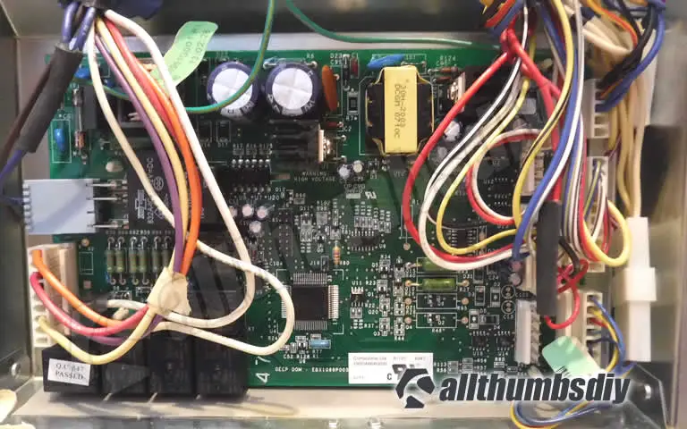
With cables – WR55X10956 -
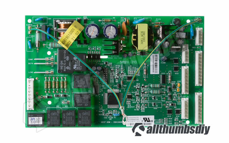
Without cables – WR55X10956
Input / Output Specifications
The principal command board is divided into two sections: Depression voltage DC side (right one-half) and 120VAC side (left one-half that contains two large capacitors). The sides are on entirely two different circuits (the reason for having ii separate greenish basis wires).
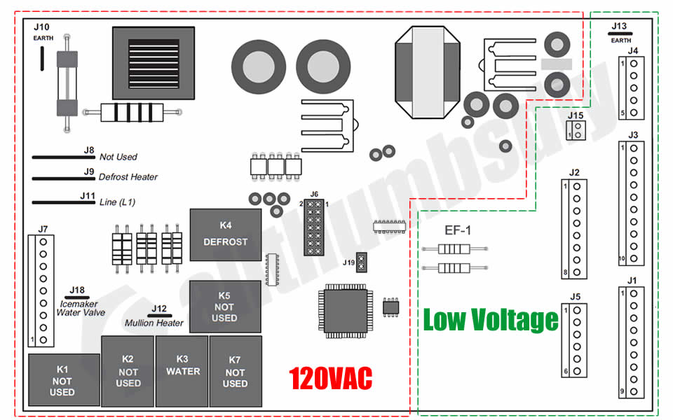
Low Voltage Side
| Jumper | Pin | Description |
|---|---|---|
| J1 (Sensor Input) | 1 | FF Thermistor |
| 2 | Ambience Thermistor | |
| iii | FZ Thermistor | |
| 4 | FZ Evap. Thermistor | |
| 5 | Thermistor Common +5V | |
| 6 | Not Used | |
| vii | Not Used | |
| viii | Model Selector | |
| 9 | Model Selector | |
| J2 (Fan Speed Control) | one | Evaporator Fan (RPM, Tachometer) |
| 2 | Model Selector | |
| 3 | Fan Common | |
| 4 | Evaporator Fan | |
| 5 | Condenser Fan | |
| 6 | Mullion Bat Heater | |
| 7 | N/A (Custom Cool Fan on certain models) | |
| viii | Fan +12V | |
| J3 | 1 | Damper |
| ii | Damper | |
| 3 | Damper | |
| four | Damper | |
| 5 | N/A (not used in PFCF1NFW model) | |
| 6 | N/A (not used in PFCF1NFW model;3 Way valve -Dual Evap) | |
| seven | N/A (non used in PFCF1NFW model;3 Way valve – Dual Evap) | |
| 8 | N/A (not used in PFCF1NFW model;3 Way valve – Dual Evap) | |
| 9 | N/A (non used in PFCF1NFW model;iii Fashion valve – Dual Evap) | |
| x | Northward/A (not used in PFCF1NFW model;3 Way valve – Dual Evap) | |
| J4 (Communications) | one | Advice ii Style Digital |
| 2 | Communication +12V | |
| 3 | Communication Mutual | |
| four | Not used | |
| 5 | Non used | |
| J5 (Not Used in PFCF1NFW) | i | North/A (Custom Cool models only; QC Damper 1+) |
| 2 | North/A (Custom Cool models only; QC Damper 1-) | |
| three | N/A (Custom Absurd models only; QC Damper 2+) | |
| 4 | N/A (Custom Cool models only; QC Damper 2-) | |
| v | +v VDC | |
| 6 | TC Thermistor (Quick Chill model merely) | |
| J13 (Earth) | i | Basis |
| J15 (Inverter) | ane | Inverter Output (4-6 VDC) |
| two | Inverter Common | |
| EF-1 (Evaporator Fan) | Northward/A | Resistors (will fire out if the evaporator fan is shorted out) |
High Voltage side
| Jumper | Pin | Description |
|---|---|---|
| J7 | ane | Non used |
| 2 | Not used | |
| 3 | Dispenser Water Valve | |
| 4 | Not used | |
| v | N/A (models w/ Quick Chill Heater) | |
| 6 | FF Light switch | |
| 7 | FZ Light switch | |
| 8 | Not used | |
| ix | Neutral | |
| J8 | 1 | Not used (supply power to compressor on certain models; PFCF1NFW uses inverter) |
| J9 | 1 | Defrost Heater |
| J11 | ane | L1 or Line 1 power supply |
| J12 | 1 | Mullion heater |
| J18 | 1 | Ice maker water valve heater |
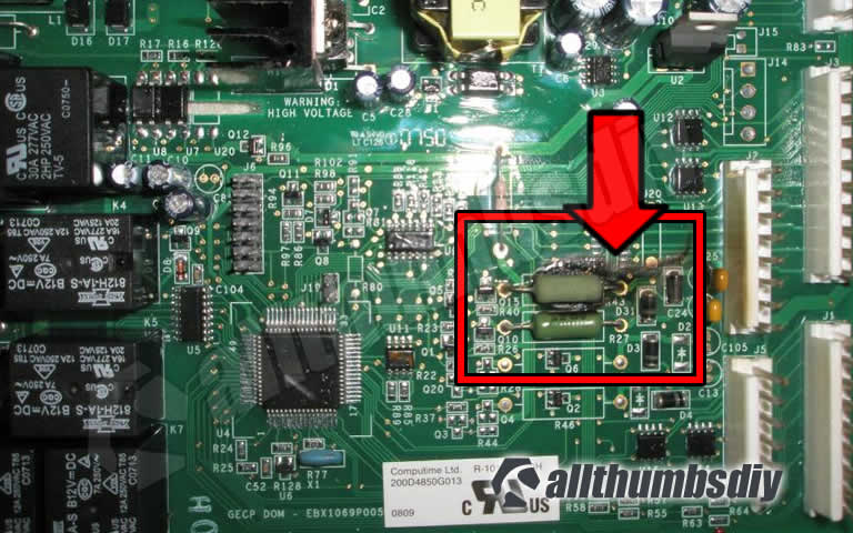
You lot should perform periodic visual inspection of your board (top and lesser sides). A healthy board should wait something like this:
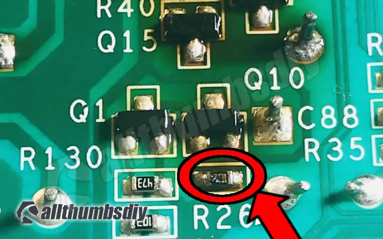
What your looking for during your visual inspection is to detect whatsoever signs of burnt components.
xxxx Some burnt components may simply be visible from the underside so you volition have to unplug your refrigerator and disconnect all wires and remove the board for closer inspection.
Primary Board Tests
- Measuring thermistor resistance at J1 jumper
- Measuring thermistor voltage at J1 jumper
Required Tools / Materials
- iii/8″ socket
- Needles nose pliers
- Multi-meter
- Ziploc bags
- Ice
- Gyre of Duct tape
- 2″ zip ties
- 4 thermistors
- 1 defrost heater temperature sensor
J1 Jumper
By the terminate of this section, nosotros want to confirm that J1 on the main board and all thermistors are in working society
- Verify that thermistor resistance is +/- 5% of sixteen.three K ohms or sixteen,300 Ohms at simulated 32 degrees
- Verify the main board J1/Pin5 is sending +5 VDC to thermistors (warning – if you are not careful, you may damage your board!)
- Verify that each thermistor is returning 2.8 to 3.5 VDC (depending on the temperature) (alert – if yous are non careful, y'all may harm your board!)
Evaporator Thermistor and Defrost Temperature Sensor
These two parts are tucked away in a very tight infinite in the freezer so it is almost incommunicable to test them in place.
My recommendation it to examination and verify that all other thermistors are in working order and that the main control board is sending a proper voltage.
Only then, skip the testing and Supercede these ii parts. At around $fifteen a piece, they are not too expensive and you will save time and lots of frustration.
Preparation Work
- Step # A1 – Fill up 3 pocket-size nix-loc bags with water ice and some h2o and set them aside for ff, fz and ambient thermistors (Pin 4 – evaporator thermistor will be replaced so it will not be tested)
- Footstep # A2 – Pull out the refrigerator and unplug information technology
- Footstep # A3 – Remove the bottom freezer door
- Footstep # A4 – For the fridge and/or freezer thermistors, remove the plastic shark gill covers by inserting a small-scale flat caput screwdriver from the bottom and popping information technology off; thermistor wire tin be pulled out almost two inches
- Pace # A5 – For the ambient thermistor, remove the toe kicking plate (below the freezer door) by removing 2 Phillips screws; you lot will need to cut off the zip tie
- Footstep # A6 – Dunk each thermistor into a ziploc bag and tape it securely to the refrigerator so that the bag volition not spill; wait 5 min
- Footstep # A7 – Uncover the primary control board access panel using a 3/8″ socket
- Step # A8 – Affect bare metal surface (abroad from the principal control board area) to discharge whatever static electricity
Measuring Thermistor – Resistance
Taking a resistance measurement with wires attached to the main board volition produce inaccurate results.
- Step # B1 – Set the multi-meter to "ohm"
- Step # B2 – Detach J1 wire harness block from the chief command lath
- Step # B3 – Insert the black lead into Pin one (FF thermistor) on the wire harness cake (non the master command board pin!); nosotros are not testing polarity and so it does not matter which atomic number 82 colour goes where;
- Step # B4 – Insert the red lead into Pivot 5 (mutual) on the wire harness block (again, non the chief control lath pin!)
- Step # B5 – Your resistance reading should be effectually xvi.3 K-ohm or sixteen,300 ohm
- Step # B6 – Repeat steps #B3 and B4 for Pins 2 and iii;all thermistors are identical and then the return resistance value should be very shut to each other;
- Footstep # B7 – If the return resistance value is way off, you can either do additional testing with the fridge plugged in (i.due east. alive voltage) or merely supersede the faulty thermistor
Warning
Although this test section involves working with the depression voltage side, you tin impairment the board, hurt or even impale yourself if you accidentally touch a wrong part! If you are uncertain of your capabilities, please consult a apparatus technician.
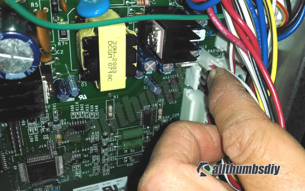
Measuring Thermistor – Voltage
Taking resistance measurements with wires attached to the chief board will produce inaccurate results.
- Footstep # C1 – Set the multi-meter to "VDC"
- Step # C2 – Leave the J1 wire harness block fastened to the main control board
- Step # C3 – Insert the black pb into Pivot 1 (FF thermistor) from the top side on the wire harness cake
- Step # C4 – Insert the ruddy lead into Pin5 from the top side on the wire harness cake
- Stride # C5 – Your return voltage reading should between 2.eight to iii.five VDC
- Step # C6 – Repeat steps #C3-four for Pins 2-iv; all thermistors are identical so the render resistance value should be very shut to each other
- Stride # C7 – If the return voltage value is fashion off, replace the faulty thermistor
Related Links
- Custom Absurd Pan Performance – How does it work? (external link, GE)
- TurboCool Operation (external link, GE)
Reader Interactions

How To Test Control Board On Refrigerator,
Source: https://allthumbsdiy.com/appliances/how-to-troubleshoot-and-replace-a-ge-refrigerator-main-control-board-wr55x10956
Posted by: denneyloges1981.blogspot.com
0 Response to "How To Test Control Board On Refrigerator"
Post a Comment